Reset Arduino Programmatically
In above said project we have implemented a robotic drive which will be of differential mode while in its movement and will be controlled simultaneously by a remote control.
DIFFERENTIAL DERIVE ROBOT :-
The term ‘differential’ means that robot turning speed is determined by the speed difference between both wheels, each on either side of your robot. For example: keep the left wheel still, and rotate the right wheel forward, and the robot will turn left. It can thus change its direction by varying the relative rate of rotation of its wheels and hence does not require an additional steering motion.
Following figure is one of the simplest illustration for the DIFFERENTIAL DERIVE ROBOT .

differentialy drive robot
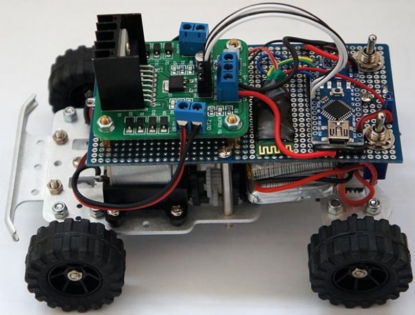
The mounting of motors on the base in the project will be as i.e two motors will be mounted on the wheels separately(one motor on one wheel).

differentialy drive robot mounting
Components used:-
- H bridges(motor drivers). Battery power source. Rf modules.
- DC motors.
- Controller (arduino/MEGA2560). Base for mounting wheels and motors. Two fixed wheels and one free wheel.
SIMULATION (VIRTUAL TOOLS) ENVIORNMENT:-
- PROTEUS ISIS
- PROTEUS ARES
- Arduino1.0.6
H bridges (Motor Drivers):-
An H bridge is an electronic circuit that enables a voltage to be applied across a load in either direction. These circuits are often used in robotics and other applications to allow DC motors to run forwards and backwards. Since we designed our H bridges(motor drivers) according to our current ratings of our motors and implemented following schematic of H bridges:

H bridge
FOLLOWING ARE THE MAIN COMPONENTS WE USED IN THE H BRIDGES
- Transistors (TIP 142, TIP 147, QN2222)
- Resistors
- Logic states(controls)
Transistors :-
We used three types of transistors in the designing of H bridge. They are TIP 142, TIP 147 and 2N2222. Transistor can be used as a switch or as an amplifier depending upon the configuration we implemented. In H bridge we use all these transistors in order to make connections using switching mode.
TIP 142
Following is the pictorial form of TIP 142.

TIP142
And the pin configuration of TIP 142 is as :

pin configuration of TIP142
Where B is base of the transistor, C is the collector and E is the emitter.
TIP 147
Following is the pictorial form of TIP 147. And the pin configuration of TIP 142 is as. Where B is base of the transistor, C is the collector and E is the emitter. Equivalent circuit which we can use instead of TIP 147 is as:

The above circuit reveals the internal packaging circuitry of the TIP 142 which consist of two simple PNP transistors, diode and resistors.
2N2222:-
Following is the pictorial form of 2n2222 AND PIN configuration of 2n2222.

2N222 pin configuation
Proteus schematic of H bridges for DIFFERENTIAL DERIVE ROBOT :
In above said project we have implemented a robotic drive which will be of differential mode while in its movement and will be controlled simultaneously by a remote control.
:
Proteus schematic of circuit of h bridge is given below :

H bridge poteus simulation
RUNNING THE SIMULATION ON
- When there is a logic combination of 00(motor A) and 00(motor B) , motor A and motor B will be static.
- When there is a logic combination of 10(motor A) and 00(motor B) , motor A will be moving in anticlockwise direction.
- When there is a logic combination of 11(motor A) and 00(motor B) , motor A and motor B will be static.
- When there is a logic combination of 01(motor A) and 00(motor B) , motor A will be moving in clockwise direction and .
- When there is a logic combination of 00(motor A) and 10(motor B) , motor A will be moving in anticlockwise direction.
- When there is a logic combination of 00(motor A) and 11(motor B) , motor A and motor B will be static.
- When there is a logic combination of 00(motor A) and 01(motor B) , motor A will be moving in clockwise direction
- When there is a logic combination of 10(motor A) and 00(motor B) , motor A will be moving in anticlockwise direction.
DC Motor:-
A simple DC motor typically has a stationary set of magnets in the stator and an armaturewith a series of two or more windings of wire wrapped in insulated stack slots around iron pole pieces (called stack teeth) with the ends of the wires terminating on a commutator .

dc motor
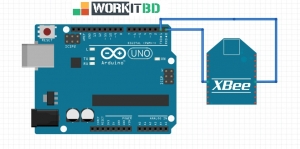
RF module
An RF module (radio frequency module) is a (usually) small electronic device used to transmit and/or receive radio signals between two devices. In an embedded system it is often desirable to communicate with another device wirelessly.

RF module
Coding:-
We implant our RF modules i.e transmitter and receiver pieces into the controller plantform to transmit and receive signals for the operations of the drive.we used AVR libraries in order to code our transmitter and receiver.
Code for transmitter DIFFERENTIAL DERIVE ROBOT:-
#define F_CPU 16000000UL #include<avr/io.h> #include<util/delay.h> #define BAUD 2400 #define ubrr 416
void USART_Transmit(unsigned int data)
{
/* Wait for empty transmit buffer */ while ( !( UCSR2A & (1<<UDRE2)) );
/* Put data into buffer, sends the data */ UDR2 = data;
}
int main()
{
UBRR2H = (unsigned char)(ubrr>>8); UBRR2L = (unsigned char)ubrr;
/* Enable receiver and transmitter */ UCSR2B = (1<<RXEN2)|(1<<TXEN2);
/* Set frame format: 8data, 2stop bit */ UCSR2C = (1<<USBS2)|(3<<UCSZ20); DDRA=0x00;
PORTA=0x00;
while(1)
{
USART_Transmit(PINA);
} }
Code for reciever part of DIFFERENTIAL DERIVE ROBOT:-
#define F_CPU 16000000UL #include<avr/io.h> #include<util/delay.h> #define BAUD 2400 #define ubrr 416
unsigned int UART_Receive()
{
/* Wait for data to be received */ while ( !(UCSR2A & (1<<RXC2)) )
;
/* Get and return received data from buffer */ return UDR2;
}
int main()
{
UBRR2H = (unsigned char)(ubrr>>8); UBRR2L = (unsigned char)ubrr;
/* Enable receiver and transmitter */ UCSR2B = (1<<RXEN2)|(1<<TXEN2);
/* Set frame format: 8data, 2stop bit */ UCSR2C = (1<<USBS2)|(3<<UCSZ20); DDRA=0xff;
PORTA=0x00; unsigned int h; while(1)
{
h=UART_Receive(); switch(h)
{
case 0b00000000:
{
PORTA=0b00000000;
break;
}
case 0b00000001:
{
PORTA=0b00001001;
break;
}
case 0b00000010:
{
PORTA=0b00000101;
break;
}
case 0b00000100:
{
PORTA=0b00001010;
break;
}
case 0b00001000:
{
PORTA=0b00000110;
break;
}
default:
{
PORTA=0b00000000;
break;
}
}
}
}
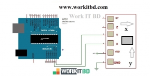
Controller platform:-
In this said project to design transmitter and receiver and the main board of the derive we will be working on adruino /MEGA2560 platform.

Arduino mega2560
We implement our RF modules into the controller plant form to transmit and receive signals for the operations of the drive.On the receiving module we further implanted our motor drivers in order to drive our robotic body.
COMPLETE SIMULATION ON PROTEUS:-
Complete simulation of the project is as follows:

differentially controlled robot using at mega2560
Related Post