Reset Arduino Programmatically
In this tutorial I’ll show you how to turn an Arduino into a clock using a 1602 LCD screen, an Arduino, a hand full of jumpers and a Real Time Clock chip/module. Great as an accessory for your desk at home or work.
The Components
- Arduino—Ideally an Uno or Duemilanove
- 1602 LCD Screen—Any HD44780 based screen works
- 1307 RTC Chip module
- Jumper cables
- Computer to program the Arduino
- Box to keep it relatively tidy in
Connecting It All Together
This project will use a number of jumper cables within a very small space so take your time to check and recheck your placements so as not to produce any magic blue smoke.
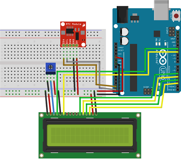
Connect the LCD to the Arduino, just to check everything works as it should. Start with the red and black power cables from the Arduino to the breadboard, and then power to the LCD screen. If you display doesn't have a backlight, ignore pins 15 and 16 on the LCD screen (the far right connectors).
LCD Connections where Pin 1 on LCD is far left:
- 1 - Ground Rail
- 2 - 5v Rail
- 3 - To potentiometer
- 4 - Digital 12
- 5 - Ground Rail
- 6 - Digital 11
- 11 - Digital 5
- 12 - Digital 4
- 13 - Digital 3
- 14 - Digital 2
- 15 (Backlight) - 5v Rail
- 16 (Backlight) - Ground Rail

The screen is based on the HD44780 chip, a very versatile chip that is used in a number of different screen sizes, ranging from 16x1 up to 40x2. All of these will work fine, the only minor adjustment required is to ensure everything lines up correctly within the code, but this is annotated to make it easy to suit to your needs.
Once the screen is wired up, you can connect the RTC module. Different modules may have a different order of pins, so check closely with your module before moving on to the next step.
Wiring up the RTC Module:
- SDA - Analog 0
- SCL - Analog 1
- 5v/VCC - 5V Rail
- GND - Ground Rail
Checking It Works
Before adding some power, it's best to double check the wiring, ensuring the power and ground cables are in the right places.
Once you’re happy, connect the Arduino. You'll see a line of black boxes on the screen. If you don't, try adjusting the potentiometer until something appears.
You should have the Arduino IDE (latest at time of writing is v1.0.5) installed on your computer. If not, visit the Arduino website to download and install.
Within the Arduino IDE, click File > Examples > LiquidCrystal > HelloWorld. A new window full of code will open. Click File and then Upload. In less than a minute the LCD will spring to life, showing Hello World and counting up every second.
You have a working screen.
Setting the Time in the RTC
You'll need to tell the RTC chip the correct time. As the chip uses a battery to keep count, it can only do this once it has a time to start counting from.
Starting with a fresh Arduino screen, copy and paste the following code, scrolling down a little to change the time to the current time.
#include "Wire.h"#define DS1307_I2C_ADDRESS 0x68byte decToBcd(byte val){ return ( (val/10*16) + (val%10) );}void setDateDs1307(byte second, // 0-59byte minute, // 0-59byte hour, // 1-23byte dayOfWeek, // 1-7 1=Mon, 7=Sunbyte dayOfMonth, // 1-28/29/30/31byte month, // 1-12byte year // 0-99){ Wire.beginTransmission(DS1307_I2C_ADDRESS); Wire.write(0); Wire.write(decToBcd(second)); Wire.write(decToBcd(minute)); Wire.write(decToBcd(hour)); Wire.write(decToBcd(dayOfWeek)); Wire.write(decToBcd(dayOfMonth)); Wire.write(decToBcd(month)); Wire.write(decToBcd(year)); Wire.endTransmission();}void setup(){ byte second, minute, hour, dayOfWeek, dayOfMonth, month, year; Wire.begin(); pinMode(13, OUTPUT); // Change these values to what you want to set your clock to. // It is best to add 30 seconds to a minute to allow time for your computer to compile and upload the current time. // Only run this script once, as running it again will overwrite the time set in the RTC chip! // Hours are in 24 hour format // Day of week starts with Monday = 1 up to Sunday = 7 // Year is in YY format, so only use the last 2 digits of the year // // Once you have run the program, the LED on pin 13 will flash to say it has finished, DO NOT UNPLUG OR RESET. // Simply follow the tutorial and upload the LCD code to avoid overwriting the correct time with this time again. // second = 0; minute = 40; hour = 21; dayOfWeek = 3; dayOfMonth = 25; month = 6; year = 14; setDateDs1307(second, minute, hour, dayOfWeek, dayOfMonth, month, year); //*/}void loop(){ digitalWrite(13, HIGH); // turn the LED on (HIGH is the voltage level) delay(1000); // wait for a second digitalWrite(13, LOW); // turn the LED off by making the voltage LOW delay(1000);}
You should add an extra 30 seconds or minute to take account of the compiling and uploading time. Click Upload to send this to the Arduino. You will only need to run this once, but if your clock goes back or forward an hour—or you move timezone/country—you will need to run the time setting sketch again.
Uploading the Time Sketch
The last step is the actual sketch that will run the clock. The only changes you will need to make is to set the date to how you would normally read it. The current script shows the date as DD/MM/20YY, to change this scroll down to the very end of the code, I have marked the 2 lines that can be changed as well as the screen
#include "Wire.h"#include <LiquidCrystal.h>#define DS1307_I2C_ADDRESS 0x68LiquidCrystal lcd(12, 11, 5, 4, 3, 2);byte bcdToDec(byte val){ return ( (val/16*10) + (val%16) );}void getDateDs1307(byte *second,byte *minute,byte *hour,byte *dayOfWeek,byte *dayOfMonth,byte *month,byte *year){ Wire.beginTransmission(DS1307_I2C_ADDRESS); Wire.write(0); Wire.endTransmission(); Wire.requestFrom(DS1307_I2C_ADDRESS, 7); *second = bcdToDec(Wire.read() & 0x7f); *minute = bcdToDec(Wire.read()); *hour = bcdToDec(Wire.read() & 0x3f); *dayOfWeek = bcdToDec(Wire.read()); *dayOfMonth = bcdToDec(Wire.read()); *month = bcdToDec(Wire.read()); *year = bcdToDec(Wire.read());}void setup(){ byte second, minute, hour, dayOfWeek, dayOfMonth, month, year; Wire.begin(); // AMEND IF YOUR USING A DIFFERENT LCD SCREEN // lcd.begin(16, 2);}void loop(){ byte second, minute, hour, dayOfWeek, dayOfMonth, month, year; String s, m, d, mth, h; getDateDs1307(&second, &minute, &hour, &dayOfWeek, &dayOfMonth, &month, &year); if (second < 10) { s = "0" + String(second); } else { s = String(second); } if (minute < 10) { m = "0" + String(minute); } else { m = String(minute); } h = String(hour); if (dayOfMonth < 10) { d = "0" + String(dayOfMonth); } else { d = String(dayOfMonth); } if (month < 10) { mth = "0" + String(month); } else { mth = String(month); } char* days[] = { "NA", "Mon", "Tue", "Wed", "Thu", "Fri", "Sat", "Sun" }; lcd.clear(); // JUMP TO CENTER ON A 16X2 SCREEN // lcd.setCursor(4,0); // CHANGE THE FOLLOWING TO SET THE DATE IN TO YOUR PREFERED ORDER // lcd.print(h + ":" + m + ":" + s); // NEXT LINE, 1 SPACE IN FROM THE LEFT // lcd.setCursor(1,1); // PREFIX THE 20 AS THE RTC CHIP ONLY USES 2 DIGITS FOR THE YEAR // lcd.print(String(days[dayOfWeek]) + " " + d + "/" + mth + "/20" + year); delay(1000); // Wait 1 second}
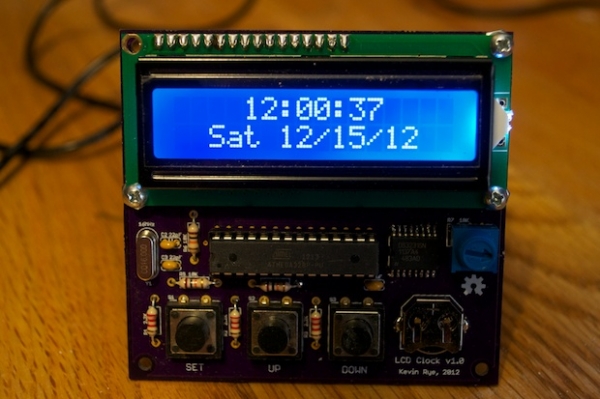
When you are happy with your changes, click Upload. Your screen will now display the current date and time, even after being unplugged.
Tidying It Up
Find a nice looking box in which to hide the Arduino and wires, add a battery or plug the Arduino into a USB charger for power (iPhone chargers work well), and there you have it, a fantastic little clock made by you.
Conclusion
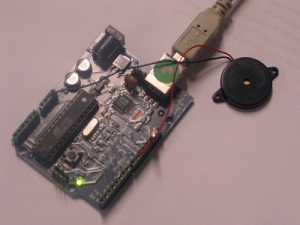
You will have a brilliant homemade clock for your desk or bedside table that won't require setting again. As it is made using an Arduino, and having 7 extra pins available you can add a buzzer, LEDs or buttons to add an alarm easily.
Expand further by controlling the backlight to turn on and off at specific times. To do this only requires you to plug 15—furthest red wire—from the LCD into a digital pin and add a time check in the code to set the pin high or low. A perfect challenge.
Related Post