Reset Arduino Programmatically
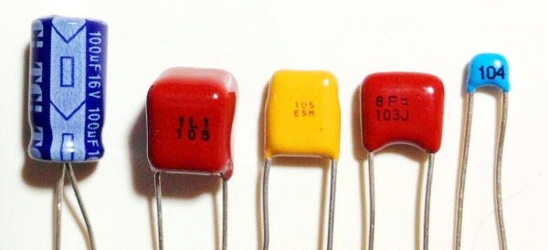
When I was testing the different Arduino capacitance meters for this post, I realized that none of them are able to accurately measure the full range of commonly used capacitors. One Arduino capacitance meter could accurately measure capacitors with values in the 1000 μF range, but it would fail with values in the nF and pF range. Another Arduino capacitance meter that accurately measured values in the nF and pF ranges failed in the μF range. Therefore, I will show you three different Arduino capacitance meters that together will cover the range of most commonly used capacitors, from about 10 pF to over 3900 μF.
In case you are interested, I tested these three capacitance meters with a range of known capacitors to compare the error in their measurements. These are the results:
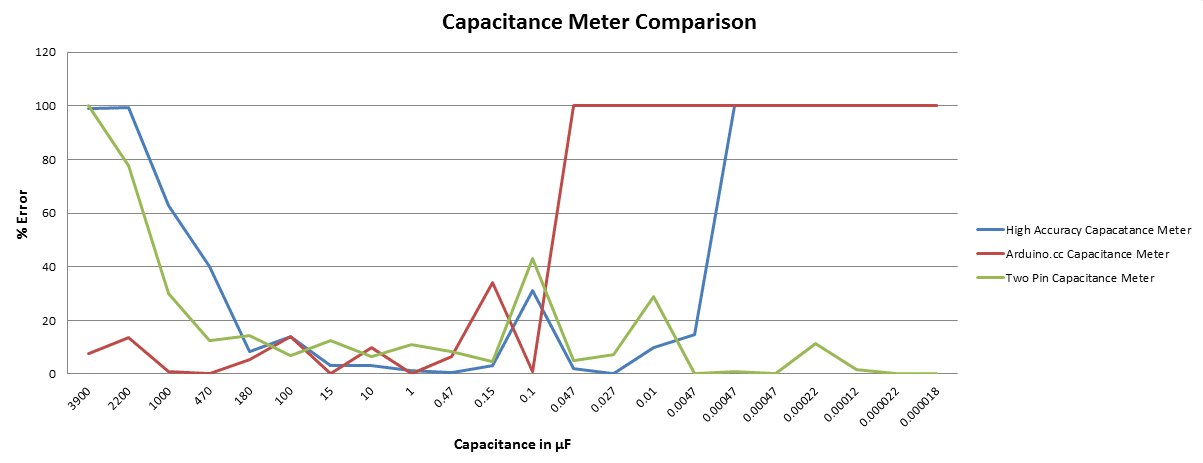
This graph makes it easy to see the range of values each capacitance meter is able to measure accurately. Since no single meter measures capacitance across the full range of common capacitors, I’m going to explain how to make each one. But first a little theory on how the Arduino is able to measure capacitance…
Arduino Capacitance Meter Theory
Capacitance is a measure of the ability of something to store electrical charge. Each Arduino capacitance meter relies on the same basic property of capacitors- the time constant. The time constant of a capacitor is defined as the time it takes for the voltage across the capacitor to reach 63.2% of its voltage when fully charged. Larger capacitors take longer to charge, and therefore have larger time constants. An Arduino can measure capacitance because the time a capacitor takes to charge is directly related to its capacitance by the equation:
TC = R x C
TC is the time constant of the capacitor (in seconds).
R is the resistance of the circuit (in Ohms).
C is the capacitance of the capacitor (in Farads).
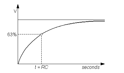
Rearranging the equation above gives:
C = TC / R
The Arduino measures the capacitance of the unknown capacitor by recording the time it takes for the capacitor to reach 63.2% of its voltage when fully charged, then dividing that value by the known resistance of the circuit.
Now we should be ready to set up the capacitance meters and start measuring some capacitors. The following are three capacitance meters, each ideal for a certain range of capacitance values.
Capacitance Meter for 1 μF to 3900 μF Capacitors
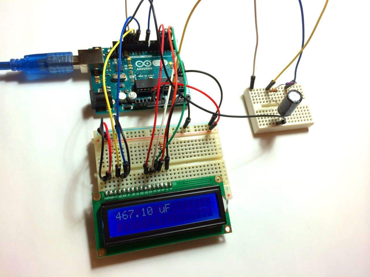
This capacitance meter is from the Arduino.cc website. After testing this meter I found that it can measure values from about 0.1 μF to 3900 μF (I didn’t test it above 3900 μF) with reasonable accuracy.
The Circuit
Follow this diagram to set up this capacitance meter:
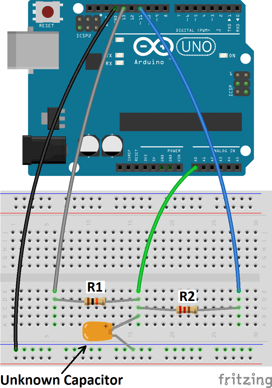
R1 = 10K Ohms
R2 = 220 Ohms
The Code
To display the readings with the Arduino serial monitor, connect the Arduino to your PC, open the Arduino IDE, and upload this code to it:
To use this meter with an LCD screen, connect the LCD to your Arduino (see How to Set Up an LCD Display on an Arduino if you need instructions). Pin 11 is already connected the LCD, so wire the capacitance meter using pin 8 instead of pin 11. Here’s the code:
Related Post

Leave Comment