Early in the study of electronics we are introduced to magnetism. The lines of force can be demonstrated by iron filings on a sheet of paper with a magnet underneath. In school science class, we made electromagnets from nails and wire. These were valuable lessons and helped us understand the principals of the telegraph, generators, relays, motors, and transducers. All of these devices produce magnetic energy to control the movement of metal objects.

COILS
Most basic of all magnetic energy producing devices is the coil. In high school general science class you probably wrapped wire around a nail to make an electromagnet. What you probably did not learn was how the gauge of the wire and the number of turns, determine the impedance of the coil.

Manufacturers looking to cut cost may change the design of their devices to accommodate a different gauge of wire they found at bargain prices, as long as the unit meets the impedance rating and power handling capacity.
RELAYS
The most basic device using magnetic energy to control things is a relay. As we see in the relay illustration, a coil wrapped around a rod acts as an electromagnet and pulls the arm of a switch when activated. This allows a low-level DC voltage to control the state of a switch from another source with out any interaction. In addition, the DC input can control high or low voltage AC or DC. Relays are rated from as low as 5 volts to as
much as a hundred volts and are used in TVs, audio equipment, and heavy industrial equipment.
TRANSFORMER
Transformers are used to step up or down the level of an AC signal. Widely used in power supplies to step down the level of 110 AC to more closely match the level requirements of solid state devices. Audio transformers accept the 1000-ohm impedance output of most low level amplifiers and convert it to an 8-ohm speaker impedance.
SPEAKERS
One of the most important devices in all of electronics is the loudspeaker. It operates on a principal of attraction and repulsion of magnetic forces. The diagram shows how the speaker is constructed. A coil is wrapped around a tube and a permanent magnet is held in place inside the tube. When an AC signal is fed to the coil, it is alternately pushed and pulled forwards and backwards. A paper cone is attached to the end of the coil to push and pull more air to produce audible sound. The suspension and spider are flexible rings that hold the cone in alignment while allowing forward and backward movement. A metal basket holds the cone in place and is connected to the magnetic assembly assuring the stable operation of the speaker.
MOTORS AND GENERATORS
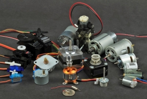
By far the most important electromagnetic devices are the motor and generator. Generators provide electrical power for our homes and all of the appliances we use, by spinning permanent magnets in close proximity to coils. Motors produce movement by manipulating magnetic coils. As a coil is drawn to a particular pole of a magnet, the polarity of the coil is changed and it is pushed away. This continual attraction and repulsion results in rotary motion. Motors are available in a wide variety of sizes and voltages and configurations at suppliers.
Motors also produce sparks that make them the number one contributor to our ozone layer. There is a Hall effect motor that does not produce sparks, which makes it ideally suited to robots that work where there are dangerous gasses in the air.
HALL EFFECT
In 1879 an American physicist Edwin Hall observed and experimented with magnetic forces and their effect on wire and metal surfaces and paved the way for the invention of many of the devices we use today.
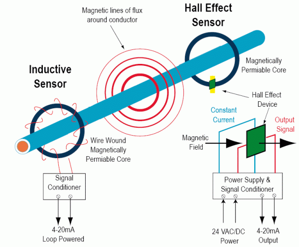
If a conductor carrying an electrical current comes in contact with a magnetic field, a voltage, know as the Hall voltage is generated across the conductor. The magnetic field distorts the natural flow of electrons through the conductor. In 1985, German physicist Klaus-Olaf von Klitzing won the Nobel Prize in physics for his expansion of Hall effect principals to semiconductor technology and discovering quantum Hall effect. As you can see in the diagram, magnetic force displaces charged particles from one electrode to another, carrying with it a flow of current from point A to point B.
Early experiments in the development of the Hall effect sensor were not very successful.
Semiconductors are made of electrons and holes that are naturally attracted to each other. To trigger a current flow through semiconductors with magnetic force was far to marginal and unstable using the doping techniques at that time. With the development of artificial semiconductor structures a matrix was designed to hold electrons and holes in thin layers of material separated by a barrier layer. With careful attention paid to new doping ratios and new material, the right chemical combination was found and a practical sensor was built. Further improvements such as signal amplification to more clearly differentiate and assure a digital output.
Although the Hall effect sensor acts like a relay, it has two specific advantages. The first is no bounce like the mechanical relay counterpart and another is that HESs can operate at very high frequencies (100k or more, and new research is continuing to expand this number).
HALL EFFECT SENSOR
The current package for the Hall effect sensor is very much like a transistor. It is a three lead in line device in a low-level transistor size black plastic case. Also available from some manufacturers is a three-pin surface mount package. Transistors have a curved back, while Hall effect sensors have a flat back. Inexpensive devices that I picked up at a surplus store had a circle on the front side to indicate the side, which comes in close proximity to magnetic sources. In the simple circuit shown, an LED with current limiting resistor will light when a magnet is brought close to the HES. If it does not, try reversing the pole. The opposite side of the sensor will respond to the other pole of the magnet.
TIMER CIRCUIT
A sensor can be used to trigger a timer for a specific duty. A Hall effect sensor is used to trigger a timer IC. When a magnetic source comes in close proximity to the HES, it supplies a negative trigger pulse to the timer. Resistor R1 acts as a positive bias for the for the input at pin 2. Timing voltage is supplied through resistor R2 and adjusted by potentiometer R3. Capacitor C1 and the adjustment of R3 determine the maximum on time. This circuit can be used as an alarm for a car or your home.
MOTOR SPEED INDICATOR
One of the most useful functions that an HES can perform is a motor speed indicator. In the diagram we see 4 magnets added to the rotor of a motor and an HES fixed in close proximity. As the magnets pass by the sensor, it clicks on momentarily, 4 clicks equal one turn, in this case. A 4027 J-K flip-flop divides the clicks by 4 to provide an accurate spin count that is then fed to a frequency counter.
There are a wide variety of frequency counters from large expensive test bench units to small circuit boards that can be incorporated in your designs and all available from surplus electronics companies like the ones listed in this magazine.
Many manufacturers of motors are including HESs in their new designs, anticipating the demands for high tech motors for new products.
CONCLUSION
The circuits here are just a few examples of how the Hall effect sensor can expand the scope of your experimentation. Research is constantly improving Hall effect sensors and the future looks amazing.
Although Hall effect sensors are not exactly standard at your local supplier, you might try a surplus electronics store or try Allegro MicroSystems, in Worcester, Mass or All Electronics Corp, P.O. Box 567, Van Nuys, CA 91408.


