Free Traffic Exchange and Free Hosting
Chances are that we would have a spare optical mouse that stopped working or partially working with the mouse buttons needing to be snubbed every time you need to click which renders your optical mouse useless. But as a DIY electronics hobbyist I tried what can we do to make the best use of the partially working mouse so that I could hack the parts from the mouse and use them for my next important project.
Look no further here is a tutorial which explains how to hack the optical sensor and that laser diode from it. DIY caps ON!!!
In this tutorial, I will show how you can handle the optical sensor inside a cheap optical-mouse for your next microcontroller project. Hope, this will allow your preferred microcontroller to look at the mouse inputs, detect surface movements, measure surface speed, etc.
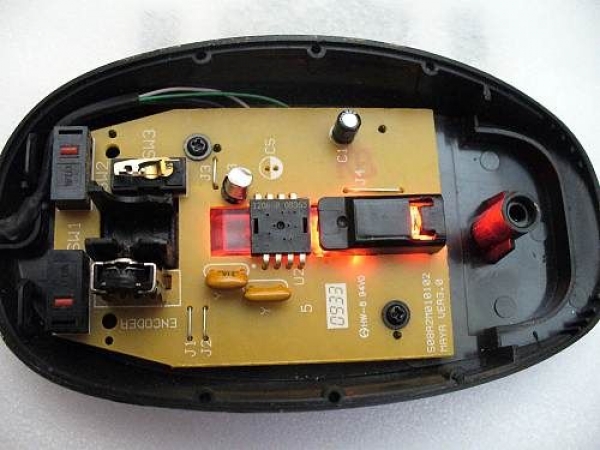
For the experiment, I opened an old usb optical mouse made by Belkin. The major component in the mouse is the ADNS-2610 Optical Mouse Sensor. There is also a controller/interface chip (HT82M99E), three microswitches, a quadrature encoder, and a red LED for surface illumination.

The ADNS-2610 is a small form factor optical mouse sensor based on optical navigation technology, which measures changes in position by optically acquiring sequential surface images (frames) and mathematically determining the direction and magnitude of movement. The sensor – from AVAGO – is housed in an 8-pin staggered dual inline package. The output format is a two wire serial port. The current X and Y information are available in registers accessed via the serial port. Resolution is 400 counts per inch (cpi) with rates of motion up to 12 inches per second (ips). Note that ADNS-2610 contains an Image Acquisition System (IAS), a Digital Signal Processor (DSP) and a two wire serial port!

Here’s a link to the datasheet of the ADNS-2610
For hacking or other experiments, we only need just two connections of the ADNS-2610 sensor (pin 3 & pin 4), in addition to the power supply (pin 7 & pin 6) terminals. A proven way to carry out this, is to extend two wires from pins 3 & 4 (SDIO & SCK) of the optical mouse sensor, and route power supply (VCC & GND) to the circuit board through the existing power supply lines marked in the printed circuit board. Remember to isolate pins 3 & 4 of ADNS-2610 from the interface/controller chip (so that the signals from the sensor pass straight through) by cutting the interconnecting copper tracks of the circuit board (refer the figure shown below). Beware, the optical mouse sensor and the LED were covered with a black protective cap. Take it off carefully!

An easy wiring method is the pretty straight forward layman’s trick. Solder wires to the four terminals of the sensor as indicated here. However, it is advisable that normal static precautions should be taken while handling this to prevent damage and/or degradation of the sensor which may be induced by ESD.

Continue To Tinker…
Yes, you can visualize optical mouse sensor data using Arduino and Processing! The Arduino code serves as a bridge between the optical mouse sensor and the PC. The Processing sketch communicates to the Arduino over the serial port and implements visualisation of the sensor data. You can find related stuff elsewhere, and here is one amazing example thrilled me a lot: https://code.google.com/p/optimouse/

If you open a standard optical mouse you will most likely find two chips inside one being a general purpose interface/controller chip and the other an optical mouse sensor. The sensor captures images of the surface below the mouse at high frame rate (1500 frames per second in the Avago ADNS2610 sensor). It uses captured images to calculate the displacement the mouse is moved over time. Incidentally, it is also able to provide the raw image data. If your mouse holds a different sensor, don’t worry too much because they are all much alike to some extent. With a bit of luck, you can work with other optical mouse sensors like PAN3101, as well.
Related Post